Ball Screw Definition and Structure
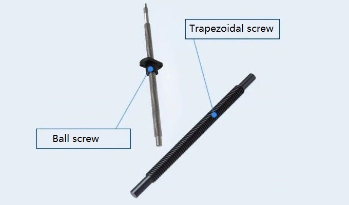
A ball screw is a commonly used mechanical transmission device that finds extensive applications in various industrial fields. It has a simple yet efficient structure that enables the conversion of rotary motion into linear motion or vice versa.
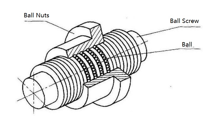
A ball screw consists of three main components: a ball screw shaft, a ball screw nut, and balls. The ball screw shaft is a long bar-like component typically made of high-strength material, exhibiting high linear precision and rigidity. The ball screw nut is a component integrated with the ball screw shaft, featuring a recirculation system that allows the balls to circulate between the shaft and the nut. The balls, which are typically made of materials such as steel or ceramics with high hardness and wear resistance, serve as the core element of the ball screw.
During operation, when the ball screw shaft rotates, the balls transmit the force through rolling motion between the shaft and the nut, thereby achieving linear motion. This transmission method offers advantages such as high efficiency, precision, and rigidity, making ball screws integral components in numerous automated systems and precision machinery.
Ball screws excel not only in their transmission performance but also in terms of their long service life, low friction, low noise, and ease of maintenance. They find wide-ranging applications in areas such as machine tools, automation equipment, aerospace, and robotics, providing reliable and efficient motion control solutions for various industrial applications.
Ball Screw's Slenderness Ratio
The slenderness ratio of a ball screw refers to the ratio between the length of the screw shaft and its diameter.
In general, for a single-end ball screw, the recommended slenderness ratio does not exceed 60 when the speed is between 1500 and 2000 RPM. For a double-end ball screw, the slenderness ratio should not exceed 40.
If the slenderness ratio is too large, it can lead to a decrease in the precision of the screw. Moreover, without appropriately reducing the speed, it can result in dangerous resonance, increased noise, reduced lifespan, and even deformation or complete failure of the screw.
The recommended slenderness ratio is based on past calculations and empirical knowledge. It allows engineers to make quick selections when the operating conditions are similar. However, for higher speed requirements or complex operating conditions, it is necessary to calculate the precise values of shaft diameter, allowable load, and lifespan by incorporating the relevant operating parameters into the permissible speed formula.
Noise generated during the operation of a ball screw: As a transmission component, ball screws inevitably produce some noise during operation. The noise characteristics vary for ball screws of different accuracy grades and manufacturing processes under the same load and speed.
Within the allowable load range, for speeds between 1500 and 2000 RPM, the noise level for C7 rolled ball screws is approximately 75 decibels, while for C10 grade ball screws, it exceeds 80 decibels. Ground ball screws exhibit noise levels around 60 decibels.
The noise level tends to increase with increasing load and speed. Therefore, in situations where strict precision requirements are not necessary, if a faster operating speed is desired, selecting a ball screw with a larger lead can improve overall system stability and reduce noise levels.
Ball Screw Selection Tips
Accuracy:
- C10 < C7 < C5 < C3
- Smaller values indicate higher accuracy, but also higher cost.
- G7 precision for rolled ball screws is commonly used and often the default choice. C5 precision achieved through grinding is a commonly used high-precision option. The price difference between C7 and C5 is typically 2 to 3 times.
Shaft Diameter:
- The outer diameter of the ball screw thread.
- Shaft diameter is related to the design load, with a focus on dynamic load.
- To ensure lifespan, the actual load should be less than the dynamic load of the ball screw, allowing for a margin under full load.
Lead (Pitch):
- The distance the nut moves along the screw axis when the screw rotates one revolution.
- Lead is related to the design speed. It is recommended to keep the speed below 1500 RPM for ball screws. If noise is not a concern, the speed can reach 2000-2500 RPM.
Parameters related to Lead:
- Pitch (P): The axial distance between two corresponding points on the thread profile along the pitch cylinder's generatrix.
- Number of threads (n): The number of helical threads on the screw. Typically, for ease of manufacturing, n ≤ 4.
- Formula: Lead = Pitch * Number of threads (S = n * P).
Length:
- Includes effective thread length and total length of the screw.
- Determine the design stroke first, then determine the thread length and total length while ensuring the slenderness ratio is less than 60 (i.e., the maximum length of the screw is less than 60 times the shaft diameter).
Note: For material limitations, when the shaft diameter is ≤φ10, the material length is 1 meter. For shaft diameters of φ12-20, the material length is 3 meters. For shaft diameters ≥φ20, the material length is 6 meters.
Selection of Shaft End:
- Determine the length (F value) and diameter (P value) based on the position of the connected coupling.
- A shorter length (F value) and a larger diameter (P value) are preferred.
Lead and Accuracy Explanation
a) The lead accuracy of ball screws is managed based on the JIS specifications (JIS B 1192-1997) as the standard for accuracy control.
b) Accuracy grades C1 to C5 are represented by linear and directional accuracy, while C7 to C10 are represented by the distance error during a 300mm travel length. The following are the error values for each accuracy grade:
C1: ±0.05mm
C2: ±0.05mm
C3: ±0.05mm
C4: ±0.1mm
C5: ±0.1mm
C7: ±0.1mm
C8: ±0.2mm
C10: ±0.3mm
These error values indicate the maximum deviation in positioning accuracy for the respective accuracy grades. It is important to consider these accuracy grades when selecting a ball screw to ensure it meets the required precision for the application.
|
Precision grade |
C1 |
|
C3 |
|
C5 |
|
C7 |
C10 |
|
Effective length of the threaded portion |
Representative travel distance error (±) |
Variation |
Representative travel distance error (±) |
Variation |
Representative travel distance error (±) |
Variation |
Performing distance error |
Performing distance error |
|
0~100 |
3.5 |
5 |
8 |
8 |
18 |
18 |
±50/300mm |
±210/300mm |
|
1 00~200 |
4.5 |
5 |
10 |
8 |
20 |
18 |
||
|
200~315 |
6 |
5 |
12 |
8 |
23 |
18 |
||
|
315~400 |
7 |
5 |
13 |
10 |
25 |
20 |
||
|
400~ 500 |
8 |
5 |
15 |
10 |
27 |
20 |
||
|
500~630 |
9 |
6 |
16 |
12 |
30 |
23 |
||
|
630~ 800 |
10 |
7 |
18 |
13 |
35 |
25 |
||
|
800~1000 |
11 |
8 |
21 |
15 |
40 |
27 |
||
|
1000~1250 |
13 |
9 |
24 |
16 |
46 |
30 |
||
|
1 250~1600 |
15 |
10 |
29 |
18 |
54 |
35 |
||
|
1 600~2000 |
18 |
11 |
35 |
21 |
65 |
40 |
||
|
2000~2500 |
22 |
13 |
41 |
24 |
77 |
46 |
||
|
2500~3150 |
26 |
15 |
50 |
29 |
93 |
54 |
||
|
31 50~4000 |
30 |
18 |
60 |
35 |
115 |
65 |
||
|
4000~5000 |
|
|
72 |
41 |
1 40 |
77 |
||
|
5000~6300 |
|
|
90 |
50 |
170 |
93 |
||
|
6300~8000 |
|
|
110 |
60 |
210 |
115 |
||
|
8000~ 10000 |
|
|
|
|
260 |
1 40 |
||
|
10000~12500 |
|
|
|
|
320 |
1 70 |