Introduction
Gear is a mechanical component consisting of toothed wheels or cylinders that mesh with each other to transmit rotational motion and torque between two or more shafts. Gears are widely used in various industries and applications, including machinery, automotive, aerospace, and robotics. They play a crucial role in power transmission and speed control.
How does Gear Work?
Gears work based on the principle of interlocking teeth. When two gears mesh together, the teeth of one gear engage with the teeth of another, transmitting rotational motion from one gear to the other. This interaction creates a mechanical advantage, allowing for changes in torque, speed, and direction of rotation.
Types of Gears
Spur Gear
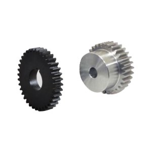
Spur gears, being the most common and simplest type of gears, feature straight teeth that run parallel to the gear axis. These gears offer efficient power transmission between parallel shafts, making them widely utilized in machinery, automotive systems, and household appliances. While spur gears are relatively easy to manufacture, it's important to note that they may generate noise and vibration, particularly when operating at high speeds.
Spur gear
Helical Gear
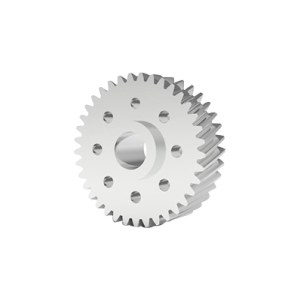
Helical gears are designed with teeth that are cut at an angle, forming a helix shape along the gear axis. This unique tooth arrangement allows for smoother engagement and operation, resulting in reduced noise and vibration levels. Helical gears excel in transmitting power between parallel shafts and offer enhanced load-bearing capabilities. As a result, they are widely utilized in heavy machinery, automotive transmissions, and various industrial applications. It's important to note that helical gears require axial thrust compensation due to their spiral tooth arrangement.
Helical gear
Bevel Gear
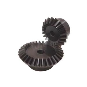
Bevel gears are specifically designed to transmit motion between intersecting shafts at a predetermined angle. These gears have teeth that are cut on conical surfaces, ensuring proper meshing and smooth operation. Depending on the intended application, bevel gears can feature straight, spiral, or hypoid teeth arrangements. They are frequently utilized in automotive differentials, steering systems, and power tools. Bevel gears excel in high torque transmission and are highly efficient in changing the direction of rotation.
Bevel gear
Worm Gear
Worm gears are commonly used in conveyor systems, elevators, and heavy-duty machinery.Worm gears consist of two main components: the worm, which is a cylindrical gear, and the worm gear, which is a toothed wheel. The worm gear features helical teeth that engage with the threads of the worm, resulting in a significant gear reduction ratio. One notable characteristic of worm gears is their ability to transmit motion and torque between shafts that are not parallel to each other. Additionally, worm gears offer self-locking properties, meaning that the worm can prevent the worm gear from rotating in the opposite direction. These gears are widely employed in various applications such as conveyor systems, elevators, and heavy-duty machinery.

Worm gear
Rack and Pinion
Rack and pinion gears are mechanical components that effectively convert rotational motion into linear motion or vice versa. The rack is a straight and flat gear with teeth, while the pinion is a small cylindrical gear. As the pinion rotates, its teeth engage with the teeth on the rack, resulting in linear movement. Rack and pinion gears find extensive use in steering systems, CNC machines, and linear actuators. These gears offer precise and efficient motion control in both directions, making them highly valuable in various applications.
Rack and pinion
Planetary Gear
Planetary gears, also known as epicyclic gears, are comprised of three main components: a central sun gear, multiple planet gears, and an outer ring gear. The planet gears orbit around the sun gear and simultaneously mesh with the ring gear. This unique arrangement enables planetary gears to deliver several advantages. Firstly, they offer high gear reduction ratios, allowing for efficient power transmission. Additionally, their compact size makes them ideal for applications where space is limited. Furthermore, planetary gears exhibit high torque capacity, enabling them to handle heavy loads. Due to these characteristics, they are widely utilized in automotive transmissions, robotics, and industrial machinery. One notable advantage of planetary gears is their exceptional load distribution, which enhances durability and efficiency. Moreover, they are capable of operating at high speeds without compromising performance. Overall, planetary gears are a versatile and reliable choice for various applications requiring efficient and robust power transmission.
Hypoid Gear
Hypoid gears are a specialized type of bevel gears characterized by their offset shaft position. Unlike traditional bevel gears, hypoid gears enable motion transmission between shafts that neither intersect nor run in parallel. Automotive differentials often employ hypoid gears owing to their impressive torque capacity. These gears facilitate smooth and efficient power transmission while effectively accommodating vertical space limitations.
Spiral Bevel Gear
Spiral bevel gears are a specific variant of bevel gears characterized by their curved teeth arranged in a spiral pattern. This unique tooth design allows for gradual engagement, resulting in exceptionally smooth operation and minimized levels of noise and vibration. Spiral bevel gears are particularly well-suited for high-speed applications that demand superior performance and reliable power transmission.
Commonly Used Gear Materials
S45C
- S45C is a steel grade used in Japan and Taiwan, equivalent to China's 45 steel.
- It is classified under the Japanese standard JISG4051-79 (94) and is a high-quality carbon steel with uniform microstructure and no structural defects.
- With a carbon content of over 0.4%, it exhibits excellent wear resistance but reduced ductility. Proper heat treatment is crucial to avoid deformation and cracking during quenching.
SUS304
- SUS304, also known as 06Cr19Ni10 or simply 304, is a commonly used stainless steel.
- It offers good corrosion resistance, heat resistance, low-temperature strength, and mechanical properties. It can be hot worked through processes like stamping and bending without hardening phenomena (usable temperature range: -196°C to 800°C).
- It is corrosion-resistant in atmospheric conditions and possesses good machinability and weldability.
- It's important to note that not all 304 stainless steels are food-grade; food-grade 304 stainless steel has stricter requirements regarding chromium, nickel, and heavy metal content.
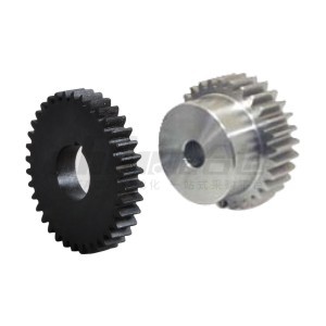
S45C / SUS304 Gear
40Cr
- 40Cr is a standard steel grade in China (GB), also corresponding to SCr440 in JIS (Japan), 5140 in ASTM (USA), and 41Cr4 in ISO.
- Widely used in the mechanical manufacturing industry, it exhibits good comprehensive mechanical properties after quenching and tempering, along with good low-temperature impact toughness and low notch sensitivity.
- It's hardenability is higher than that of 45 steel, making it suitable for manufacturing components subjected to high loads, impacts, and medium-speed operation, such as gears, spindles, oil pump rotors, sliders, and bushings.
20CrMnTi
- 20CrMnTi is a high-performance carburizing steel with high hardenability. After carburizing and quenching, it develops a hard and wear-resistant surface with a tough core, exhibiting high low-temperature impact toughness.
- It is used in the manufacturing of important components subjected to high-speed, medium, or heavy loads, impacts, and friction, such as gears, gear rings, and gear shafts.
- It serves as a substitute for 18CrMnTi and is widely used in carburized parts with matching heat treatment processes involving carburizing and shot blasting.
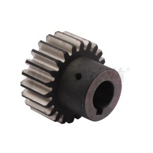
20CrMnTi Gear
POM (Polyoxymethylene)
- Also known as acetal resin or polyformaldehyde, POM is a thermoplastic crystalline polymer often referred to as "super steel."
- It has a smooth, glossy, hard, and dense surface, typically appearing in light yellow or white. It can be used in a temperature range of -40°C to 100°C for prolonged periods.
- POM exhibits superior wear resistance and self-lubricating properties compared to most engineering plastics, along with good resistance to oil and peroxides. However, it is not resistant to acids, strong alkalis, or UV radiation.
- Its tensile strength reaches 70 MPa, it has low water absorption, and it maintains dimensional stability and gloss. These properties surpass most types of nylon. Highly crystalline, POM is the toughest among thermoplastic resins, offering high resistance to heat, bending, fatigue, wear, and electrical properties.
MC901
- MC Nylon, also known as cast nylon, is an engineering plastic widely used for its exceptional properties.
- Known for its lightweight, high strength, self-lubricating, wear-resistant, and corrosion-resistant nature, MC Nylon is extensively applied in various fields.
- MC901 (blue): This modified nylon 6, characterized by its distinctive blue color, offers higher toughness and flexibility compared to regular cast nylon. It has excellent fatigue resistance, making it an ideal material for gears, racks, and transmission gears.
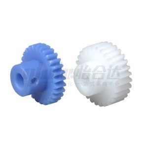
MC Nylon Gear
Features of Gear
- High Transmission Power: Gears, especially spur gears, can handle significant power transmission. They are suitable for applications that require high torque transmission and power transfer.
- Fixed Center Distance: Gears have a fixed centre distance between the mating gears. This design ensures stable operation and contributes to the longevity of the gear system. Gears with a fixed centre distance are commonly used in compact structures and high-reliability mechanisms.
- Gear Tooth Size: The gear teeth size is typically expressed using the module (m), a unit specified by the International Organization for Standardization (ISO). However, other methods may also denote the size of gear teeth.
- Module: The module multiplied by pi (π) gives the pitch diameter (d). The pitch diameter is the diameter of the imaginary circle that passes through the gear teeth. It determines the distance between adjacent teeth.
- Pressure Angle: The pressure angle is a parameter that determines the shape of the gear teeth. It represents the inclination of the gear tooth surface. The standard pressure angle is generally 20 degrees, although 14.5-degree pressure angle gears were common in the past.
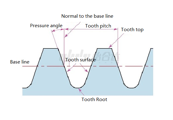
- Number of Teeth: The number of teeth on a gear is counted using graphical methods. For example, the gear with ten teeth can be represented as "=10".

- Addendum and Dedendum: The height of the gear tooth is determined by the module (m). The International Organization for Standardization (ISO) and the Japanese Industrial Standards (JS) define the gear tooth form, specifically the full-depth tooth.
- The following terms describe the dimensions:
Addendum (h): The height from the tooth tip to the base circle. h = 2.25m (sum of the working depth and dedendum).
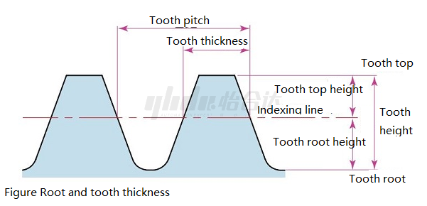
The height of the top of the tooth (ha) is the height from the top of the tooth to the indexing line (center line). *The indexing line is the reference line for calculating the rack dimensions.
ha = 1.00 m
Tooth root height (hf) is the height from the tooth root to the index line (center line). hf = 1.25 m
The tooth thickness ( s ) is based on half of the tooth pitch ( p ). * Tooth pitch ( p ) = m
s = T m / 2
Example:
Calculate the tooth height (h) / tooth top height (ha) / tooth root height (hf) for a gear of module 2. h = 2.25 m = 2.25 × 2= 4.50
ha = 1.00 m = 1.00 x 2 = 2.00hf = 1.25 m = 1.25 x2= 2.50(8) Diameter of the gear (size of the gear)
The parameter that determines the size of the gear is the diameter of the indexing circle of the gear (d ). Using the index circle as a reference, the tooth pitch, tooth thickness, tooth height, tooth top height, and tooth root height are determined.

- Gear Meshing and Terminology: The meshing of gears refers to the engagement between the teeth of two gears. Here are some common terms used in gear systems:
Pitch Circle: The theoretical circle that passes through the contact points between the mating gears.
Addendum Circle: The circle that defines the outer limit of the gear tooth.
Dedendum Circle: The circle that defines the inner limit of the gear tooth.
The top and root circles presented here can be seen directly, while the indexing circle cannot be seen directly on the actual gear. This is because the indexing circle is a circle assumed to determine the size of the gear.
Example of calculation.
Calculate the diameter of the index circle/top circle/root circle of a spur gear with modulus ( m ) 2 and tooth number (z) 20. d = zm = 20 × 2 = 40
da = d + 2m = 40 + 4 = 44df = d - 2.5 m = 40 - 5 = 35
Gear mesh and the name of each part

Calculation of Gear
|
Item |
Symbols |
Calculation formula |
Pinion |
Large Gear |
|
Module |
m |
- |
2.5 |
|
|
Pressure Angle |
0X |
20° |
||
|
Number of Teeth |
Z |
15 |
30 |
|
|
Pitch Circle Diameter |
d |
zm |
37.5 |
75 |
|
Addendum |
ha |
1.00m |
2.5 |
2.5 |
|
Dedendum |
hf |
1.25 m |
3.125 |
3.125 |
|
Whole Depth |
h |
2.25 m |
5.625 |
5.625 |
|
Outside Diameter |
da |
d +2m |
42.5 |
80 |
|
Root Diameter |
df |
d-2.5m |
31.25 |
68.75 |
|
Center Distance |
a |
d1+d2/2 |
56.25 |
|
What's the Difference Between Gears and Sprockets
Gears and sprockets are mechanical components used for power transmission and motion control. While they serve similar purposes, there are some key differences between gears and sprockets:
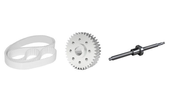
- Shape and Design: Gears have teeth that are specially shaped and arranged on a cylindrical or conical surface. These teeth mesh with the teeth of another gear to transmit power and motion. On the other hand, sprockets have teeth that are evenly spaced and designed to engage with the links of a chain or a belt.
- Mechanism of Power Transmission: Gears transmit power and motion through teeth meshing. The teeth of the driving gear engage with the teeth of the driven gear, causing the rotational motion to transfer from one gear to another. Sprockets, on the other hand, transfer power through the engagement of their teeth with the links of a chain or a belt, enabling the sprocket to rotate and transmit motion.
- Application: Gears are commonly used where precise speed control, torque transmission, and angular positioning are required. They are found in various devices such as automobiles, machinery, watches, and gearboxes. Sprockets, on the other hand, are primarily used in systems that involve chains or belts, such as bicycles, motorcycles, conveyor systems, and industrial machinery.
- Load Distribution: Gears distribute the load across multiple teeth, producing smooth and efficient power transmission. The teeth of the gear engage simultaneously, distributing the load evenly. In contrast, sprockets distribute the load to individual chain or belt links, which may cause higher stress on specific contact points.
- Size and Construction: Gears are available in various sizes and constructions, including spur, helical, bevel, worm, rack and pinion, and planetary gears. Sprockets, on the other hand, have a more standardized design and are often manufactured with a simpler construction due to their compatibility with chains or belts.

In summary, while gears and sprockets are used for power transmission, gears have specially shaped teeth that mesh, while sprockets engage with chains or belts. Gears are more versatile in design and application, while sprockets are commonly used in systems involving chains or belts.
Advantages and Disadvantages of Gears
Advantages of Gears:
- Efficient power transmission with minimal energy loss.
- Precise control over speed and torque.
- Wide range of gear types and sizes for diverse applications.
- Compact design allows for space optimization.
- Relatively low maintenance requirements.
Disadvantages of Gears:
Gear systems can be complex and require precise alignment for proper operation.
Noise and vibration may occur, especially with certain gear types or misalignments.
Gears may require lubrication and periodic maintenance.
Higher costs associated with gear manufacturing and assembly.
How to Choose the Right Gears
When choosing spur gears, the following factors are generally considered:
- Selection of module and number of teeth: Choose the appropriate module and number of teeth based on the desired gear ratio and space limitations, ensuring that the gear size and transmission performance meet the requirements.
- Space requirements of the installation location: Consider the space limitations where the gears will be installed and choose gear sizes that are suitable for installation.
- Gear load torque requirements: Select the appropriate gears based on the load torque requirements of the transmission system, ensuring that they can withstand the required torque.
- Selection of internal hole shape: Choose the appropriate one, such as a keyway or round hole, based on the gear's installation method and connection requirements.
- Material selection: Select the appropriate material, such as stainless steel (SUS304), carbon steel (S45C), or nylon, based on the environmental conditions and application requirements. This ensures the durability and performance of the gears.
- Temperature requirements of the surrounding environment: Consider the temperature requirements of the application scenario and choose gears with high-temperature or low-temperature resistance properties to ensure their reliability under different temperature conditions.
- Requirements for surrounding media, dust protection, electrostatic discharge, noise, etc.: Select gears with appropriate characteristics, such as corrosion resistance, dust protection, anti-static properties, and low noise, based on specific application requirements.
- Material hardness requirements: Choose the appropriate material hardness based on application needs and the hardness requirements of the gear's operating environment. This ensures the gear's strength and wear resistance.
By considering these factors when choosing spur gears, you can ensure that the selected gears meet the application requirements and provide reliable transmission performance.
Applications of Gears
Automotive industry: Gears are used in transmissions, differentials, and steering systems.
Industrial machinery: Gears are employed in conveyors, pumps, generators, and machine tools.
Robotics: Gears are crucial for precise motion control and positioning.
Aerospace and defence: Gears are used in aircraft engines, landing gear systems, and military equipment.
Consumer electronics: Gears are utilized in cameras, printers, etc.

Conclusion
In conclusion, gears are versatile and fundamental components in many industries and applications. Their advantages in power transmission, motion control, and load-bearing capabilities make them indispensable. By understanding the different gear types, their features, and the factors to consider when choosing gears, one can make informed decisions to optimize system performance.
Take the next step towards efficient and reliable mechanical systems by selecting the appropriate gears for your specific application. Consult with industry experts or gear manufacturers to ensure the best gear selection for your needs. Maximize your system's performance and productivity by harnessing the power of gears.
Contact us today at to explore our wide range of gear solutions and receive expert guidance for your gear selection needs. Elevate your mechanical systems to new heights with the right gears – contact us now!


