Straightness is a fundamental geometric property used to ensure that a part's linear elements maintain an ideal straight form. It is often synonymous with flatness, signifying the extent to which the element remains within specified limits of being straight. Straightness tolerance establishes the maximum permissible deviation between the actual line and the ideal straight line. This tolerance is defined without the requirement of a datum reference.
1. Forms of Straightness Callout
In Geometric Dimensioning and Tolerancing (GD&T), straightness serves two distinct purposes based on its callout method. The first form is Surface Straightness, which regulates the form of a line at a specific location on a surface or feature. The second form is Axis Straightness, controlling the permissible curvature of the axis of a part. Typically, the callout includes the maximum material condition (MMC) requirement.

2. Basic Descriptions
Surface Straightness:
Surface Straightness, defined by a two-dimensional tolerance, ensures uniformity across an entire surface or feature. This concept applies to flat features (like a block's surface) or can be oriented along the axial direction for cylindrical surfaces. It specifies the tolerance zone within which the specified line on the surface should reside.
Axis Straightness:
Axis Straightness governs the straightness of the center axis of a part. It is, in fact, a three-dimensional tolerance that constrains the part's central axis to prevent excessive bending or twisting. When applying MMC to Axis Straightness tolerance, the given tolerance value is for when the feature is at its largest material condition. This means that the positional tolerance can increase when the actual size of the feature deviates from its maximum material condition.
3. Tolerance Zone
Surface Straightness:
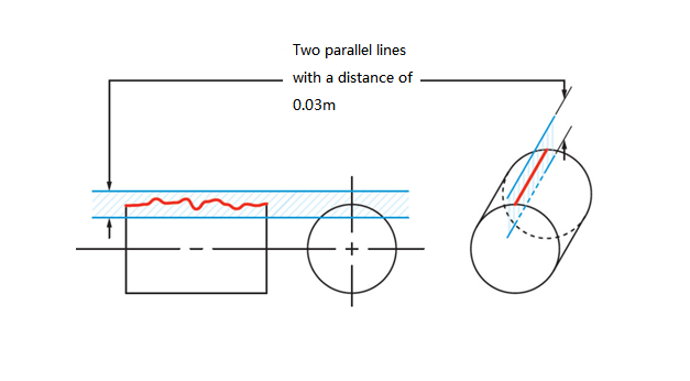
The tolerance zone for Surface Straightness is the region between two parallel lines at a distance equal to the tolerance value (e.g., 0.03mm).
Axis Straightness:
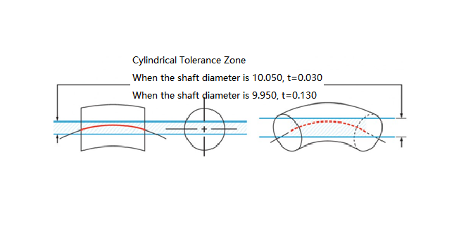
For Axis Straightness, the tolerance zone is a cylindrical region. The actual axis of the feature must remain within this cylindrical surface with a diameter of 't'. (Considering MMC, size tolerances can compensate for the positional tolerance value—additional tolerance equals the difference between the maximum material condition and the actual part size.)
4. Measurement
Surface Straightness:
To measure Surface Straightness, secure the part and use a gauge to measure along the straight line. Changes in the measured height can reveal deviations from a straight line along the surface.

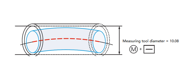
Axis Straightness:
For Axis Straightness, a cylindrical measuring tool is used to ensure that the part or feature remains straight along the axis. This tool helps determine whether the part is within the total envelope of the maximum material condition. This measurement method controls both diameter and axis straightness.