Tolerance is the allowable variation of the actual parameter value of a part in mechanical design and manufacturing. If the upper and lower limits of a certain part are 100 and 60 respectively, then its tolerance is 40. If the upper and lower limits are +100 and -100 respectively, then its tolerance The tolerance is 200.
Tolerance is the allowable variation in the actual parameter value of a part in mechanical design and manufacturing. During the processing of parts, due to machine tool accuracy, tool wear, measurement errors and other reasons, it is impossible to limit the processing error of the part size within a certain range and specify the amount of dimensional variation.

Tolerance related terms:
1) Basic size
The dimensions are determined during design based on the strength and structural requirements of the part.
2) Actual size
Dimensions obtained by measurement.
3) Extreme size
Two limits for allowed size variation. It is determined based on the basic size. The larger of the two limit values is called the maximum limit size, the smaller one is called the minimum limit size.
4) Dimensional deviation (referred to as deviation)
The algebraic difference obtained by subtracting a certain size from its base size. Dimensional deviations include:
Upper deviation = maximum limit size - basic size
Lower deviation = minimum limit size - basic size
The upper and lower deviations are collectively called limit deviations, and the upper and lower deviations can be positive, negative or zero.
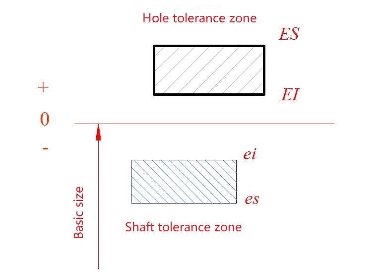
National standards stipulate that the upper deviation code of the hole is ES, the lower deviation code of the hole is EI. The upper deviation code of the shaft is es, and the lower deviation code of the shaft is ei.
5) Dimensional tolerance (referred to as tolerance)
Variation in dimensions allowed.
Dimensional tolerance = maximum limit size - minimum limit size = upper deviation - lower deviation
Because the maximum limit size is always greater than the minimum limit size, that is, the upper deviation is always greater than the lower deviation, the dimensional tolerance must be positive.
6) Zero line, PR zone and tolerance zone diagram
The zero line is a reference line used to determine the deviation in the tolerance zone diagram, that is, the zero deviation line. Usually the zero line represents the basic dimension. Mark "0", "+", and "-" on the left end of the zero line. The deviation above the zero line is positive. The deviation below the zero line is negative.
The tolerance zone is an area bounded by two straight lines representing upper and lower deviations. The width and position of the tolerance zone are the two elements that constitute the tolerance zone.
7) Standard tolerance and standard tolerance grade
Standard tolerance is any tolerance listed in national standards to determine the size of the tolerance zone. Standard tolerance levels are levels that determine the degree of dimensional accuracy. The standard tolerance is divided into 20 levels, namely IT01, IT0, IT1~IT18, which represents the standard tolerance. The Arabic numerals represent the standard tolerance level. Among them, IT01 level is the highest, the levels decrease in order, and IT18 level is the lowest. For a certain basic size, the higher the standard tolerance level, the smaller the standard tolerance value, and the higher the accuracy of the size.
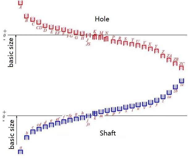
8) Basic deviation
Used to determine the upper or lower deviation of the tolerance zone relative to the zero line position. Generally refers to the deviation close to the zero line. When the tolerance zone is above the zero line, the basic deviation is the lower deviation. When the tolerance zone is below the zero line, the basic deviation is the upper deviation.
According to actual needs, the national standard stipulates 28 different basic deviations for holes and shafts, as shown in the figure below. The basic deviation values of holes and shafts can be found from the relevant tables.
In actual product design, reasonable determination of tolerances is the key to ensuring that products are manufactured with excellent quality, excellent performance and low cost. Regarding the determination of tolerances, there are basically three methods:
• Calculation method: Precision instruments often refer to design materials, mechanical design manuals and other theories to perform detailed manual calculations to determine tolerances.
• Analogy method: In most cases, tolerances in equipment manufacturing industries with slightly larger products are determined based on actual past experience (these experiences are accumulated through R&D proofing verification and iterative summary of products).
• Software-assisted method: Another method is to use tolerance determination software for determination. Currently, it is widely used in the automotive industry. Most companies in the domestic manufacturing industry do not use this type of software. But this is the future trend!
When determining tolerances, tolerance principles must also be followed. Tolerance principles refer to the provisions on the allowable deviation range for elements such as size, shape, and position during the manufacturing process in order to ensure the interchangeability and functionality of parts. The purpose of the tolerance principle is to ensure that parts can match each other during assembly and use, and to ensure the stability of their functions and performance.
1) Principle of independence
The principle of independence is a principle that the geometric tolerance and dimensional tolerance given in the drawing have nothing to do with each other. They are given separately, measured separately, and meet the requirements separately. It is mainly used for non-fitting parts or situations where the shape and position are strict and the dimensional accuracy is relatively low.
There are element dimensions that do not meet the requirements, such as part outline dimensions, pipeline dimensions, and process structure dimensions, such as undercut dimensions, thread endings, rounding, chamfer dimensions, etc. There are also element dimensions that do not have dimensional tolerances marked.
2) Inclusion requirements
The containment requirement means that the actual feature is everywhere within the containment surface of the project shape. The size of the project shape is MMS (maximum solid size). At this time, it should comply with the MMB (maximum solid boundary). It is mainly used in occasions where there are coordination requirements and the coordination properties need to be guaranteed.
The adoption of tolerance requirements is mainly to ensure the fit properties, especially precision fits with small fit tolerances. Use the maximum solid boundary to comprehensively control the actual size and shape errors to ensure the necessary minimum gap (to ensure free assembly) or the maximum interference. Use the minimum physical size to control the maximum gap or minimum interference amount (interference fit) to achieve the required fit properties. Such as the journal and sliding bearing of the rotary shaft, the sliding sleeve and hole, the fit of the slider and the slider groove, etc.
3) Maximum physical requirements
The maximum solid requirement is a tolerance principle that controls the actual contour of the measured element to be within the maximum solid effective boundary. That is, when the actual size deviates from its maximum physical size, the geometric error value can exceed the geometric tolerance value given on the drawing.
If MMR (Maximum Solid Requirement) is applied to the measured element, the geometric tolerance value of the element is given when the part is in MMC (Maximum Solid State). As long as the maximum solid requirement is applied, the maximum solid effective boundary must be adhered to the actual size If it deviates from the MMVS (maximum physical effective size), the geometric error value is allowed to be compensated.
The maximum physical requirement is established on the basis of assembly interchangeability. It is often used for parts with low precision (low dimensional accuracy and low shape and position accuracy) and loose requirements for mating properties, but requires parts that can be assembled freely to obtain maximum technical benefits. Manager benefits, such as: controlling the position tolerance of the center of screws, bolts, etc.
4) Minimum entity requirements
The minimum material requirement is a tolerance principle that controls the actual contour of the measured feature to be within the LMVB (minimum material effective boundary). That is, when its actual size deviates from the LMS (minimum physical size), the geometric error value can be compensated.
Minimum entity requirements are mainly used when the strength or minimum wall thickness of the part needs to be ensured. If LMR (minimum solid requirement) is applied to the measured element, the geometric tolerance value of the element is given when the part is in LMC (minimum solid state), as long as LMR (minimum solid requirement) is applied, the LMVB (minimum solid requirement) must be complied with effectiveness boundary).
When its actual size is equal to the minimum physical size, the geometric tolerance is equal to the given value. When its actual size deviates from the minimum physical size, the excess value is allowed to be compensated for the geometric tolerance, and the maximum compensation amount is its dimensional tolerance value.
5) Reversibility requirements
The reversible requirement is that when the geometric error value of the measured axis or center plane is less than the given geometric tolerance value, the corresponding dimensional tolerance is allowed to increase without affecting the function of the part. That is, the geometric tolerance is allowed to be compensated for the dimensional error (counter-compensation).
The reversible requirement cannot be used alone. It is usually applied together with MMR (Maximum Material Requirement) or LMR (Minimum Material Requirement). At this time, the measured element should comply with MMVB (Maximum Material Effectiveness Boundary) or LMVB (Minimum Material Effectiveness Boundary).