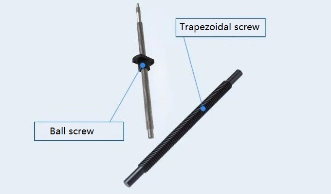
1. 30 Degree Trapezoidal Screw
Trapezoidal screw is a type of screw transmission. Movement and power are transmitted through the screwing of the nut and the screw, which can convert rotational motion into linear motion. The trapezoidal screw has the characteristics of high transmission efficiency, accurate positioning, and large load-bearing capacity. The rotary motion is converted into linear motion through the screw screw and the engaged nut, and energy and force are transmitted at the same time.

2. Summary of 30 Degree Trapezoidal Screw Names


| Parameter | ||
| Serial Number | Name | Code |
| 1 | Nominal Diameter | d |
| 2 | Pitch | P |
| 3 | Crest Clearance | ac |
| 4 | Crest Height | H1 |
| 5 | External Thread Height | h3 |
| 6 | Internal Thread Height | H4 |
| 7 | External Thread Major Diameter | d2 |
| 8 | Internal Thread Major Diameter | D2 |
| 9 | External Thread Minor Diameter | d3 |
| 10 | Internal Thread Minor Diameter | D1 |
| 11 | Internal Thread Large Diameter | D4 |
| 12 | Root Width | b |
3. Characteristics of 30-Degree Trapezoidal Screw
1) Simple structure, convenient processing and relatively economical price
2) When the thread rise angle is smaller than the friction angle, it can self-lock
3) Smooth transmission
4) Large friction resistance, efficiency range between 0.3~0.7, in self-locking state, efficiency range below 0.4
5) Has specific resistance to impact and vibration
6) The load capacity is higher than that of ordinary rolling spirals.
4. Selection Review Calculation
For general force-transmitting screws, the main failure modes are thread surface wear and screw breakage under tensile stress.
Cracks, shears, and shearing or bending of thread roots. The design is mainly based on wear resistance calculation and strength calculation.
Identify the main dimensions of the screw drive.
For conductive spirals, the failure mode is mainly caused by excessive gaps or deformation due to wear.
The movement accuracy decreases. When designing, the wear resistance of the thread and the stiffness of the screw should be calculated to confirm the screw.
Main dimensions of the transmission. If the conductive spiral is subject to a significant axial load simultaneously, additional strength calculations are required.
Long screws (with a slenderness ratio exceeding 40) that are not manually adjusted may produce lateral vibrations, and their specifications should be checked.
Limit speed.
For the convenience of description, the following are the relevant parameters and simple calculations designed in the formula calculation.
|
Serial Number |
Parameter Name |
Symbol |
Unit |
Calculation Formula |
Related Parameter 1 |
Related Parameter 2 |
Related Parameter 3 |
|
1 |
Lead |
S |
mm |
S = N × P |
N - Number of threads |
P - Pitch |
/ |
|
2 |
Middle Diameter |
d2 |
mm |
d2 = D - 0.5P |
D - Axial diameter |
P - Pitch |
/ |
|
3 |
Helix Angle |
α |
degrees |
α = arctan(S / (π × d2)) |
S - Lead |
π - Pi (3.14) |
d2 - Middle Diameter |
|
4 |
Self-locking Judgment |
/ |
/ |
a < fa |
a - Angle |
fa - Static friction angle |
/ |
|
5 |
Screw Efficiency |
η |
/ |
η = (1 - μ × tanα) / (1 + μ × tanα) |
μ - Static friction coefficient |
tanα - Tangent of helix angle |
/ |
|
6 |
Contact Surface Pressure |
Pm |
MPa |
Pm = F / P0 |
F - Axial load |
P0 - Allowable dynamic thrust |
/ |
|
7 |
Sliding Speed |
V |
m/min |
V = (π × d2 × n / cos α) × 10^-3 |
π - Pi (3.14) |
d2 - Middle Diameter |
n - Speed |
|
8 |
Output Torque |
T |
Nm |
T = F × P × 10^-3 / (2 × π × n) |
F - Axial load |
P - Pitch |
n - Efficiency |
5. Precautions for use
1) Load instructions
Avoid additional radial loads, which may cause abnormal operation, increased wear, sintering jam, etc.
2) Dust-proof requirements
Prevent foreign matter from entering. If iron filings, tin slag, aluminum filings, etc., are likely to be generated during working conditions, a protective cover should be added to prevent
Foreign objects entering the threads can cause abnormal wear or jamming.
3) If the slenderness ratio of the screw exceeds a certain range (slenderness ratio is above 60), it will produce a certain curvature due to its weight.
The nut produces a radial unbalanced load. Depending on the specific speed and torque used, it will cause abnormal wear, jamming, and shaft damage.
If the ends are bent or broken, anti-bounce devices can be used in the middle to restrain them.
4) Selection of lubricant, see the table below for details
|
Operating Conditions |
Type of Lubricating Grease/Oil |
|
Low Speed: High Load |
Lithium Grease 2#~3# |
|
Medium Speed - Medium Load |
Lubricating Oil 68#~100# or Lithium Grease 1#~2# |
|
High Speed: Light Load |
Lubricating Oil 32#~68# |
5) Pay attention to fixation when installing - support the coaxial and level adjustment of the installation method; fixation - free cantilever structure
The structure should pay attention to the control of shaft end tolerance and the locking and fixation of the head.
6) When installing the trapezoidal thread screw, a runout check must be performed. If there is no suitable measuring equipment,
equipment, then the screw should be moved by hand one or several times along its entire length before installing the original moving parts;
If the force required for the outer diameter of the shaft is uneven, accompanied by signs of wear, it indicates that there is a gap between the screw and the nut support.
Rails are misaligned. In this case, first loosen the relevant mounting screws and then move the wires by hand. If the required force is now even, calibrate the corresponding part again, otherwise it should be loosened again. Install the screws to determine the calibration error.